Precision Semiconductor & Laser Optical Infrastructure
Direct factory supply of certified fused silica, quartzware, and electro-optical components manufactured under tight process control.
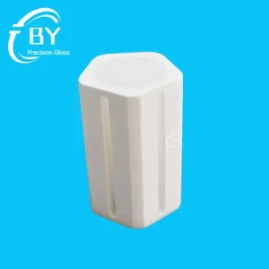
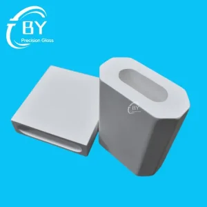
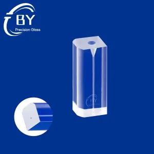
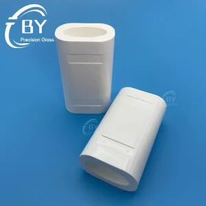
Next-Gen Optoelectronic Interconnect: The W-Groove Quartz Paradigm
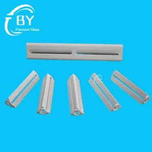
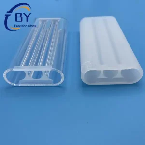
In high-bandwidth photonic packaging, the standard V-groove architecture often introduces asymmetric shear stress and thermal expansion drift during high-temperature reflow or epoxy curing. The advanced W-Groove Quartz Substrate features double-recessed micro-channels precisely etched or diamond-diced into high-purity synthetic fused silica (JGS1/Corning 7980 equivalent).
Thermally Matched Stability
Features an ultra-low coefficient of thermal expansion (CTE of 0.5 × 10⁻⁶/K), eliminating fiber misalignment issues across thermal cycling ranges from -40°C to +125°C.
Sub-Micron Pitch Tolerances
Proprietary multi-axis CNC grinding and chemical polishing maintain groove pitch tolerances within ±0.25 μm and angular apex deviations under 0.1°.
Symmetric Stress Dispersion
The W-groove profile provides balanced dual-contact anchoring, mitigating epoxy-induced core shifts during automated active fiber array alignment.
China Factory 4.0: Scalable Precision & Supply Chain Resilience
Combining end-to-end hot/cold fabrication under one roof to deliver high yields, compressed delivery lead times, and deterministic traceability for global Tier-1 telecom and datacom OEMs.
Deterministic Traceability
From synthetic ingot melt analysis to multi-sensor optical profilometry, each substrate batch ships with raw material and CMM coordinate certs.
In-Line High-Speed Metrology
Laser confocal interferometers and automated non-contact optical comparators guarantee 100% inspection on critical groove depth and surface roughness.
Vertical Integration
Cold-working slicing, high-vacuum ultrasonic cleaning, high-temperature annealing, and cleanroom packaging run seamlessly within our Tianjin complex.
Dynamic Ramp Velocity
Scalable tooling allows transition from prototype pilot lines (2-3 weeks) to volume scale (>50,000 units/month) with zero tooling re-qualification bottlenecks.
Engineering Benchmark: Substrate Material Performance
Evaluation of substrate matrices for high-channel dense fiber arrays in 800G / 1.6T transceivers and LiDAR modules.
| Performance Parameter | High-Purity Quartz (JGS1) | Standard Silicon (Si 100) | Borosilicate Glass | High-Precision Alumina |
|---|---|---|---|---|
| Thermal Expansion (CTE × 10⁻⁶/K) | 0.54 (Optimal matching) | 2.60 (Moderate drift) | 3.25 (Substantial expansion) | 7.20 (Severe CTE stress) |
| Optical Insertion Loss Drift (-40°C~+85°C) | < 0.08 dB | < 0.25 dB | > 0.45 dB | > 0.80 dB |
| Refractive Index Matching (at 1550 nm) | 1.444 (Matches silica fiber) | 3.476 (Severe Fresnel bounce) | 1.472 (Acceptable) | 1.750 (Reflective mismatch) |
| UV Transmission (Curing Epoxy Access) | > 90% at 365 nm | 0% (Opaque - blind curing) | > 82% at 365 nm | 0% (Opaque) |
| Micro-Groove Chipping & Breakage | Zero chipping (<0.5μm) via chemo-polish | Prone to cleavage along crystal plane | Medium microcracking risk | High grain pullout risk |
Global Sourcing Demands & Commercial Realities
Optical interconnect market expansion driven by hyperscale AI clusters and edge automation has fundamentally reshaped substrate procurement criteria.
AI Server Architecture Shift
Large AI computing clusters (supporting GPUs and TPUs) are migrating to Optical I/O and CPO to eliminate copper signal attenuation. These high-density architectures demand 16-channel, 32-channel, and 64-channel fiber arrays built on micro-structured W-groove substrates with extreme cumulative pitch tolerance.
Silicon Photonics Integration
Silicon photonic transceivers require ultra-compact fiber coupling. Using transparent quartz allows technicians and automated pick-and-place cameras to view alignment fiducials through the substrate, slashing packaging cycle times by over 40% compared to silicon baseplates.
Procurement Risk Mitigation
Global procurement teams prioritize Tier-1 manufacturers that run integrated crystal raw ingot sourcing, computer-controlled precision slitting, and internal cleanroom QA to hedge against supply chain volatility, customs delays, and quality batch rejections.
Localized High-Impact Application Scenarios
Engineered for precision alignment in demanding operational environments across industrial, medical, and data communications platforms.
Co-Packaged Optics & Transceivers
Deployed in 800G/1.6T transceivers where multi-channel polarization-maintaining (PM) or single-mode fibers require exact alignment to edge-emitting lasers and planar lightwave circuits (PLC).
- Transmits 365 nm UV light for rapid resin fixation
- High return loss (>55 dB) configuration
Autonomous LiDAR Emitter Arrays
Automotive-grade LiDAR packages require tight laser diode to optical fiber routing that survives mechanical shock, extreme operating vibrations, and wide engine-bay thermal swings.
- Withstands sustained -40°C to +125°C cycling
- High mechanical shear resistance
Biomedical Spectrophotometry
Precision multi-capillary diagnostic instruments and sequencing flow cells rely on inert fused quartz substrates to route excitation laser wavelengths with zero auto-fluorescence.
- Zero UV degradation or background noise
- Immune to solvent/acid biochemical corrosion
Technical & Sourcing FAQ
Comprehensive answers regarding materials, tolerances, engineering design, and volume manufacturing.
What is the structural advantage of a W-Groove over a standard V-Groove quartz block?
Which quartz and fused silica grades do you use for high-speed optical substrates?
What are your manufacturing capabilities regarding channel count and pitch pitch accuracy?
Can the quartz substrate facilitate backside UV adhesive curing?
What quality certification and metrology documentation accompany shipments?
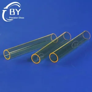
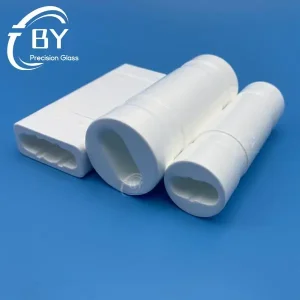
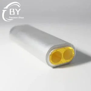
Specialized Flow Tubes, Cavities & Optical Quartz Assemblies
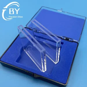
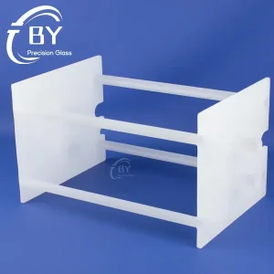
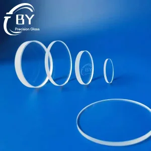
Explore our integrated production line of industrial glass components, flow handling cells, and lithography optics.