Precision Engineering Portfolio · Series I
High-Purity Quartzware & Optical Subassemblies
Ultra-low thermal expansion, high breakdown voltage components machined under strict cleanroom conditions for high-vacuum and plasma processing.
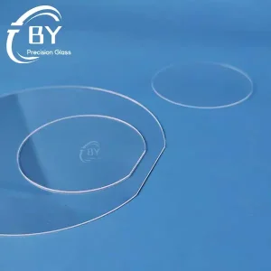
Custom Borofloat 33® Glass Wafers for Semiconductor Manufacturers
View Specifications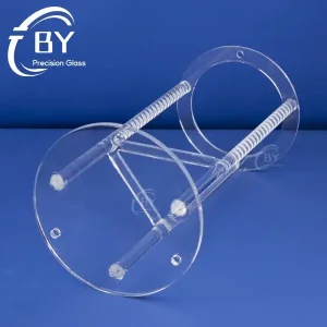
Wholesale Quartz Wafer Carriers for Semiconductor Suppliers
View Specifications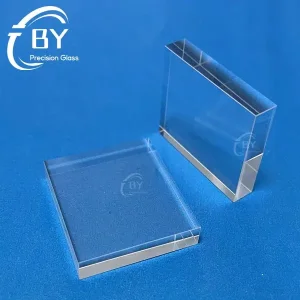
Custom Sapphire IPL Light Guide Block Used for Laser IPL Handles
View Specifications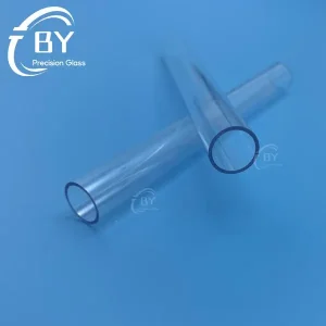
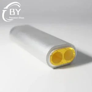
Wholesale Cerium Doped Quartz Tube Blocked UV Wavelength
View Specifications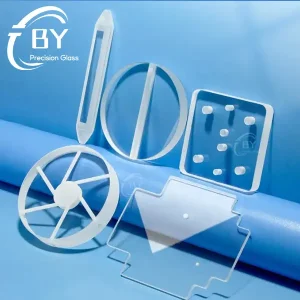
Wholesale High Temperature Custom Quartz Glass Fabrication
View Specifications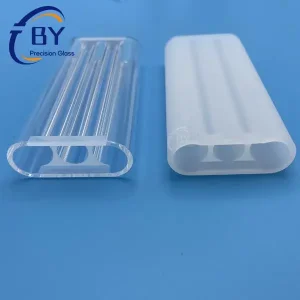
Candela Laser Head Triple Bore Chamber Assembly In Stock
View Specifications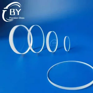
Wholesale Quartz Optical Windows for Lithography Equipment
View Specifications
Industrial Landscape Analysis
Commercial Status of Ion Source Quartz Liners
Critical consumable components bridging atomic ion generation and wafer yield integrity across sub-7nm node semiconductor manufacturing and precision mass spectrometry.
In modern vacuum plasma equipment, an ion source quartz liner serves as the primary sacrificial dielectric barrier separating high-density, energetic plasma discharges (ranging from electron cyclotron resonance [ECR] and radio-frequency [RF] inductively coupled sources to Bernas-style filament discharge arcs) from the grounded metallic chamber chassis. Without ultra-high-purity quartz sleeves and liners, direct ion bombardment releases host transition metal contaminants—including Fe, Cr, Ni, and Cu—into the ion beam stream, inducing catastrophic lattice lifetime defects in semiconductor silicon substrates.
The global commercial ecosystem for custom quartz liners has experienced profound disruption driven by geopolitical realignment, advanced node transitions (FinFET to GAAFET nanosheets), and the expansion of Compound Semiconductor (SiC/GaN) high-energy implantation. Fabrication plants operate under stringent Mean Time Between Failures (MTBF) and Mean Time to Clean (MTTC) imperatives. Ion source liners must withstand intense heat fluxes, halide chemical attack from gaseous feedstocks (such as BF3, PH3, AsH3, SiF4, and GeF4), and cyclical thermal shocks during arc ignition and de-energization.
Key Engineering Fact: Over 72% of unexpected ion implanter chamber contamination incidents stem not from feedstock degradation, but from micro-crack devitrification and flaking on interior quartz liner surfaces caused by incompatible coefficient of thermal expansion (CTE) mismatches or excessive hydroxyl (OH) radical outgassing under high-vacuum operation (< 10-6 Torr).
Purity & Contamination Defense
Fabricated using Class A synthetic fused silica (SiO2 > 99.9999%) and electrically fused natural quartz. Stringent elimination of heavy metals prevents wafer cross-contamination during ultra-shallow junction (USJ) doping.
- ICP-MS validated trace alkali metal control (Na, K, Li < 0.5 ppm)
- Zero heavy element leaching under harsh fluorine/chlorine cleaning
- Passivated fire-polished or ultra-fine acid-etched inner surfaces
Thermal & RF Plasma Resilience
Engineered to handle extreme thermal gradients exceeding 900°C across millimeters of wall thickness while maintaining high RF power coupling efficiency without dielectric breakdown.
- Near-zero linear thermal expansion coefficient: 5.5 × 10⁻⁷ /°C
- Resistant to thermal spalling during high-frequency plasma pulsation
- High loss-tangent stability ensuring maximum electromagnetic penetration
Precision Micro-Machined Features
Complex mechanical geometries produced via ultrasonic 5-axis CNC machining, maintaining dimensional integrity across gas manifold orifices, mounting keys, and pyrometer viewing windows.
- Tight concentricity and runout tolerances held to within ±0.02 mm
- Custom slotted gas distributor injection ports without micro-chipping
- Oxyhydrogen flame-welded flange collars annealed for zero stress birefringence
Material Engineering Benchmark
Comparative Performance of Ion Chamber Materials
Evaluating dielectric, chemical, and thermal properties for synthetic fused silica, natural quartz, and engineering ceramics inside ion beam generators.
| Material Category | Purity (SiO₂ / Base) | OH Content | Max Working Temp | Dielectric Strength | Halogen Plasma Resistance | Contamination Risk |
|---|---|---|---|---|---|---|
| Synthetic Fused Silica (JGS1) | > 99.9999% (< 0.1 ppm Fe) | < 5 ppm to 1200 ppm (Grade Opt) | 1,100 °C | 25–35 kV/mm | Superior | Zero Trace Leaching |
| Electrically Fused Natural Quartz (JGS2) | > 99.995% (< 1.5 ppm Fe) | < 30 ppm (Standard Low-OH) | 1,150 °C | 20–25 kV/mm | Excellent | Extremely Low |
| Gas-Refined Optical Quartz (JGS3) | > 99.99% (< 3 ppm Fe) | < 5 ppm (Water-Free IR) | 1,200 °C | 20–25 kV/mm | Very High | Low |
| High-Purity Alumina (99.8% Al₂O₃) | N/A (Oxide Ceramic) | Negligible | 1,600 °C | 15–20 kV/mm | Moderate (Particulates) | Al Contamination Risk |
| Hot-Pressed Boron Nitride (PBN) | N/A (Nitride Ceramic) | Zero | 1,800 °C (Vacuum) | 30–40 kV/mm | Moderate | Boron Outgassing Hazard |
Annealing Strain Point
1,070 °C
Thermal Conductivity (20°C)
1.38 W/(m·K)
Refractive Index (nd)
1.458
Mohs Hardness
7.0 (Non-porous)
Direct Mission-Critical Deployments
Localized Fab & Laboratory Applications
From high-volume commercial semiconductor foundry floors to space simulation test facilities and analytical secondary ion mass spectrometers.
Semiconductor Ion Implantation
Operating inside high-current, medium-current, and high-energy implanters (Axcelis Purion, Varian VIISion, Applied Materials VIISta architectures). Liners shield the source housing from intense arc currents, isolating toxic BF3 and AsH3 plasmas.
Ion Beam Etching & Sputter Deposition
Kaufman and broad-beam RF ion sources utilized in thin-film magnetic recording head fabrication, optical thin-film interference filter coating, and surface planarization in bulk acoustic wave (BAW/SAW) RF resonators.
High-Resolution Mass Spectrometry
Installed within ICP-MS (Inductively Coupled Plasma Mass Spectrometry) and SIMS (Secondary Ion Mass Spectrometry) ionization tubes, providing absolute chemical neutrality to measure parts-per-quadrillion isotopic ratios.
Satellite Gridded Ion Propulsion
Xenon and krypton propellant discharge chambers for space flight electric thrusters. Liners survive multi-year continuous microwave plasma excitation in vacuum without dielectric breakdown or embrittlement.
Future-Ready Engineering Pathways
Technology Roadmap: Sub-2nm Nodes & Beyond
How quartz material processing is evolving to overcome the physical limits of plasma sheath degradation and high-aspect-ratio wafer doping.
1. Controlled Surface Micro-Texturing Against Flaking
As implant cycle runtimes expand, vaporized dopants and sputtered cathode tungsten redeposit onto the cool quartz liner walls. Once stress accumulates, these conductive films flake off, causing catastrophic electrical arcing across high-voltage grids. Next-generation quartz liners implement precision micro-bead blasting and acid-etched anchor profiles (surface roughness Ra maintained between 2.5 µm and 4.0 µm). This micro-topography provides mechanical anchoring, locking conductive deposits onto the liner walls and doubling operational lifetime before maintenance shutdowns.
2. Extreme Low-Hydroxyl (OH < 1 ppm) Thermal Densification
Under continuous exposure to fluorine radicals (F*), Si-OH bonding terminations act as catalytic breakdown nodes, yielding accelerated volatile SiF4 etching and hydroxyl contamination in ultra-high vacuum environments. By leveraging multi-stage electrical vacuum melting and hydrogen-free zone refining, low-OH synthetic quartz reduces chemical sputtering rates by up to 34% compared with conventional flame-drawn quartz tubes.
3. Hybrid ALD / CVD Protective Enamels
Leading manufacturing research explores applying atomic layer deposition (ALD) yttria (Y2O3) or scandium oxide nanocoatings on precision-ground quartz liners. This architectural fusion combines the zero-CTE thermal shock immunity of fused silica bulk bodies with the chemical inertia of rare-earth oxides against fluorine plasma attack.
Integrated Manufacturing Workflow
Factory Production Standards & QA Protocols
From custom CAD drawing review to cleanroom hermetic packaging, our end-to-end processing eliminates dimensional drift and surface micro-fractures.
Drawing Review & FEA Modeling
Every custom liner begins with thermal stress simulation and Design for Manufacturability (DFM) verification. Engineers optimize corner fillets and transition radii to eliminate localized thermal concentration nodes under discharge heating.
Diamond CNC & Flame Polishing
Multi-axis diamond tooling contours the raw quartz ingot. Complex through-holes and gas inlets are cut with ultrasonic assist, followed by oxyhydrogen flame polishing to fuse microscopic surface fissures.
Stress Annealing & CMM Inspection
Full-cycle programmable thermal annealing relaxes internal stress gradients. Every finished liner undergoes coordinate-measuring machine (CMM) verification, laser interferometry, and cleanroom vacuum double-bagging.
Comprehensive Engineering FAQ
Ion Source Quartz Liner Procurement & Tech Q&A
Detailed technical guidance answering real-world fab engineering, QA, and procurement inquiries.
Why is quartz selected over ceramic (Al₂O₃) for ion implanter arc chambers?
Alumina (Al2O3) contains aluminum ions that can easily be sputtered by high-energy back-streaming ions into the wafer batch, causing severe deep-level metallic contamination in silicon. Fused quartz consists entirely of silicon dioxide (SiO2); sputtered material matches native wafer chemistry, avoiding device-killing parasitic doping.
How does hydroxyl (OH) content affect liner performance in vacuum?
High-OH quartz (> 200 ppm) outgasses water vapor (H2O) and oxygen under deep vacuum (< 10-6 Torr) and elevated temperatures. This outgassing oxidizes tungsten or molybdenum filaments, causing premature filament burnout. We recommend low-OH natural quartz (JGS2/JGS3, OH < 20 ppm) for thermal ion sources.
What dimensional tolerances can your CNC facility hold on custom liners?
With multi-axis ultrasonic diamond grinding equipment, we routinely hold outer and inner diameters to ±0.015 mm, wall thickness concentricity within 0.02 mm, and angular hole orientation within ±0.1°. All critical sealing steps can be fine-lapped to achieve a surface roughness of Ra < 0.2 µm for reliable elastomeric O-ring sealing.
How is thermal stress managed during flame working of complex liners?
Oxyhydrogen flame welding introduces localized thermal stress points. All our hot-worked quartz assemblies undergo a multi-step programmable annealing schedule up to 1,150°C followed by controlled furnace ramping down to 400°C. Each batch is 100% verified using cross-polarized photoelastic strain meters to guarantee near-zero residual birefringence.
Can you manufacture replacement liners for obsolete OEM ion sources?
Yes. We offer complete reverse engineering support. Customers can supply either original CAD geometries (STEP, IGES, DWG) or send physical, worn, or broken liner samples. Our optical CMM systems capture accurate 3D geometry, allowing us to produce 1:1 functional drop-in replacements with optimized material grades.
What cleanroom packaging protocols are used for export shipments?
All finished quartz parts undergo multi-stage ultrasonic deionized water cleaning and hot N2 purging. Finished parts are double vacuum-sealed in Class 100 cleanroom-grade antistatic polyethylene bags with shock-absorbent custom foam enclosures to prevent shipping damage and micro-particle contamination.
Precision Engineering Portfolio · Series II
Advanced Optical & Semiconductor Components
Full suite of engineered glass, capillary structures, and custom-fabricated quartz devices serving global photonics and semiconductor equipment factories.
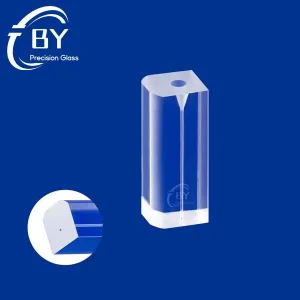
Custom Fiber Optic Glass Ferrules Supplier, Factories
View Specifications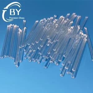
High-Quality Quartz Substrate Groove for Optical Couplers
View Specifications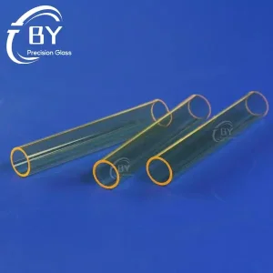
UV Block Yellow Quartz Tube for IPL Lamp Flow Handle
View Specifications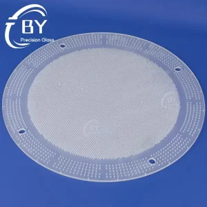
Custom Optical Quartz Gas Distribution Plate Manufacturer
View Specifications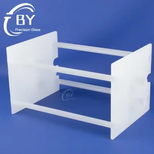
Wholesale Quartz Diffusion Boat for Semiconductor Suppliers
View Specifications
Precision Custom Quartz Glass Components for Semiconductor
View Specifications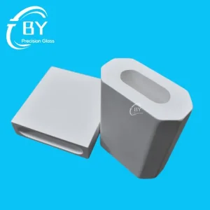
Diffuse Reflectors Made of Spectralon-Grade PTFE
View Specifications